Behold the unholy marriage between an old wrecked reed organ and a SID chip.
Features:
62 keys, monophonic CV/SID or polyphonic Midi. No touch sense.
Adjustable keyboard split high/low.
Individual envelope and arpeggio and glissando for each keyboard split.
2 LFOs. Sine only so far.
4 Control rods assignable to a lot of different functions and parameters.
Built in MOS6581 SID chip. You know. 3 channels triangle/saw/square/noise and all.
4 0-10V CV out for Euro Rack module control.
2 gate inn/out for Euro Rack control and external arpeggio sync.
10 save slots for settings (pre-named after C64 games from A to J)
some stuff i can’t recall…
I found the old reed organ in a really sorry state after at least a year outdoors in the Norwegian rain. It was already on its way to the trash yard, and the keyboard was so swelled it looked like a sine wave. I knocked it apart and kept only the keyboard section.
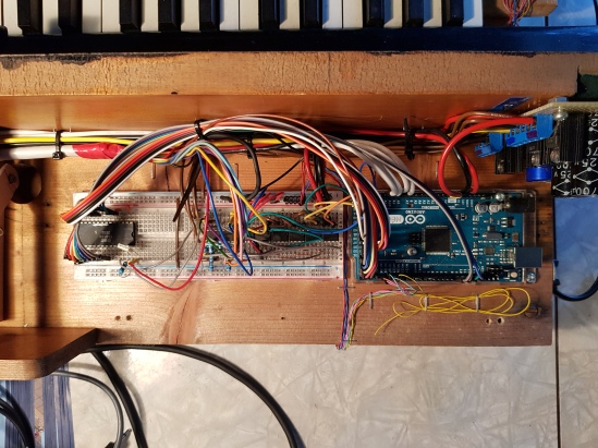
I have mounted pushbuttons and springs under each key. Instead of a keyboard grid I have used PCF8574 expansion boards (which I happened to have a pile of) making the whole keyboard I2C interfaced. An Arduino Mega takes it from there.
The sound is generated from a MOS6581 SID chip controlled straight from the Arduino Mega, but it can also 1V/octave control external oscillators trough one of the four CV outputs. I have made room and power for a few eurorack modules at the right side. At the moment I only use a reverb unit which I control with CV out patched to one of the Sound Rods, and patch the SID audio output trough this. Yes, and a home made eurorack master clock so I can sync arpeggio with my Ditto guitar looper.
The old sound control rods are connected to potentiometers and sent to the AIs on the Mega. The transmission only moves the potentiometer a few degrees so the voltage difference is quite small. I have compensated somewhat for that by changing the analog reference voltage as low as possible so I don’t waste to much resolution.
I have used one of the tiny 128×64 oled displays from ebay, together with an encoder, to allow serious menu diving. There is A LOT of settings available so far, so this unfortunately necessary. I would really want a bigger display, but that would require more memory for the display library and I’m already dangerously low on RAM.
On the software side I had some challenges with the multi-level menu system and the lack of memory, forcing me to learn more about pointers. Which is a good thing I guess. I have made my own Arduino libraries both for the menu system and the SID, only the latter anywhere near clean enough to share with you guys.
Problems so far:
The SID and CV-out circuits is a breadboarded rats nest and not trustworthy.
The Mega is almost out of memory. The oled library takes a lot. The menus take the rest.
The Mega is to slow to allow smooth LFO/Envelope/Appergio/Glissando processing together with menu operation. Glitching occurs and resources are maxed out. Okay, maybe with tons of optimization but ain’t Nobody Got Time for That!
The filter of the SID chip does not work. Yes they are bought on Ebay.
The +/-12V power supply made from scrap transformers gets dangerously hot. Also it is a bit hummy which you might notice on the video. I have used it for hours with no problem but I am afraid it will burn down the house if I forget to switch it off.
Future plans:
Replacing the Mega with a Teensy to satisfy my need for speed and memory. I am not planning on any audio processing in the teensy, only menus and control signals.
Getting a bigger display. Menu diving on the tiny oLed is mildly cumbersome.
Designing and printing some PCBs for the SID and the CV out, trough Dirty PCBs. Both cards will be I2C controllable to save pins and to avoid level shifting a million pins from 3V3 to 5V if I move to teensy.
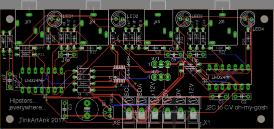
To clean up my Sid Organ, I have designed a simple card for my SID chips, allowing I2C control. The card will be addressable from 0-3 allowing 4 SID cards on the same bus.
The card is supplied from +/- 12V to fit the eurorack standard but with the option of single power if wanted. There is also a jumper to choose between MOS6581 and MOS8580, the latter using 9V power supply. I think.
There are, maybe unnecessary, +/-9V regulators to clean up the power supply output buffer in case of noisy power rails. These can be bypassed.
Summary:
Selectable single or dual 12V supply.
Addressable up to 4 SIDs on same bus. Actually up to 8 if you use PCF8574B on half the cards.
Buffered Audio Output. Audio can be attenuated with resistors.
Optional 9V regulators for clean power to the output buffer.
Jumper for MOS6581 / MOS8580 selection.
I2C control. I will update my own Arduino SID library to fit this communication.
Two auxiliary power outputs i.e. for driving a clutch in a future version
On board potensiometer and buttons for manual test driving and configurations
Bidirectional isolated RS485 port for remote control. Now programmed for my own “tinkarBus” from a master Arduino controlling the installation, but software adaptable for direct DMX in the future.
The PCB has been made by pad2pad. I’m not to experienced with PCB design so using Pad2pads own routing software keeps me from doing stupid mistakes or mixing inches with mm etc. Hva used them twice now and are very satisfied.
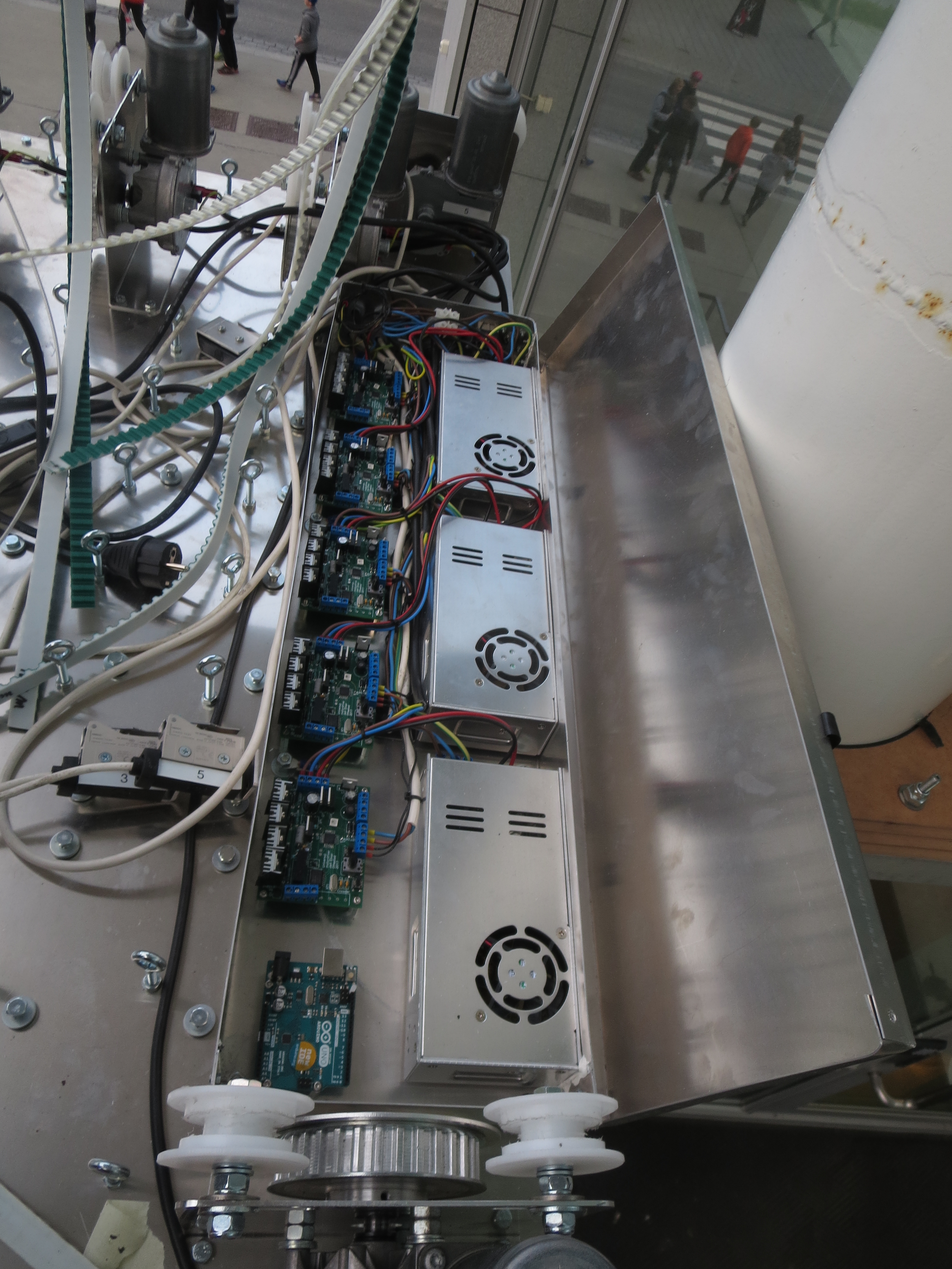
The installation itself is a rather complex net of pulleys and counter weights, making a lot of movements out of few motors. On the video above only four motors are used, but Lawrence aim to use nine motors making more complex patterns.
You will notice that two of the pictures have sepia tone instead of colors. This is not photoshopped, but actually how it looks thanks to the use of monochromatic Sodium Lights which are old tunnel street lamps. There was only on problem: They need a long warm up time before reaching full strength.
I therefore made cardboard shutters (the lamps are quite cool so no fire hazard) for all the lamps, to allow quick transitions between the scenes.
All parts of plywood except the small cogwheels made of 10mm teflon I happen to have in my workshop. They are controlled by simply reversing the voltage. End switches in both positions are bypassed with diodes so they only stop on direction.
Edit: Now including a short video of me playing it!
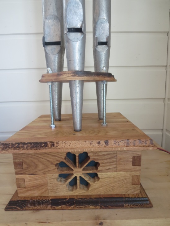
Bought three organ pipes second hand on ebay the other day. Pitches (from lower key) are C, D and F#. Decided to make an electric organ out of it.
Case are made of oak wood milled on my CNC milling machine with church like ornament windows. It is my first experiment with making simplified tapped corners on the CNC machine. Not perfect but it seems to work out. On one side there is a control panel with individual power adjustment for each pipe plus vibrate frequency and depth.
I have used an Arduino to control the fan motors because I’m lazy. It gives me the possibility to PWM control and modulate the pipes with a few mosfets (IRLZ24N) and minimum effort. If I want to add midi control in the future, this will also be straight forward.
I have used separate fans, from hot air guns, mounted straight under each pipe. This gives a really simple assembly with no valves to worry about. The down side is that the fan noise is quite audible trough the pipe sound.
All in all I am very happy with the looks of this thing. Less happy with the sound, and the possibilities are obviously quite limited with only three pipes.
I am quietly daydreaming of buying a full set of old church pipes to make a huge Serafin like contraption of it. The biggest problem so far seems to be that the parts must be transported from the USA to Norway, which is far from cheap.
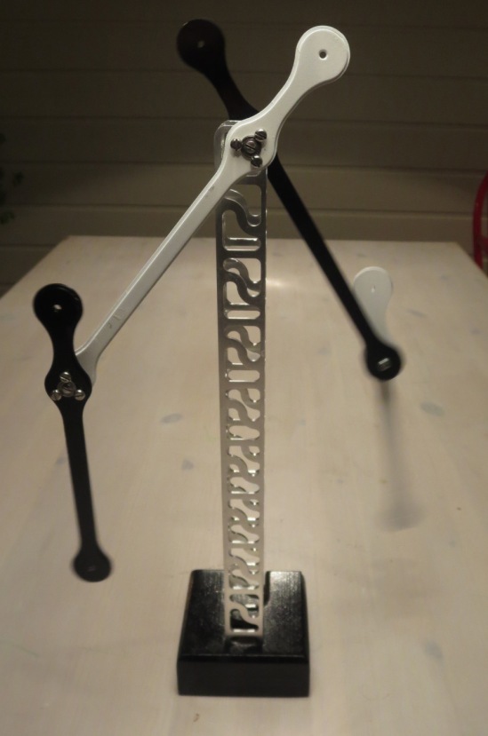
Grethe Mo was producing a solo theatre performance about (fear of) math. She wanted some kind of visual effect to visualize the beauty of math and numbers. Quick brainstorming with Anne-Sophie Eriksen and Kjersti Høgli led to this:
A table mounted double pendulum. Ironically enough a demonstration of chaos; where the math and numbers break down.
The devise is made by home milled aluminium leftovers from the Grenland Friteater storage. All joints have ball bearings to give a long lasting pendulum. The finish of the bare aluminium parts are gently sanded to give a matte look and to remove scratches from the old materials.


